Trolley Bypass System Rules (as of March 2017)
This system will operate in two modes: one trolley only with no stops in bypass and two trolley mode with each waiting until the other arrives at the bypass.
The polarity of the track approaching the bypass will determine the turnout position of the incoming approach.
The first trolley to arrive at its sensor, stops its own power, reverses the track power behind which also throws the turnout behind that trolley and waits for the second trolley.
When the second trolley covers its sensor, the track power will reverse behind it which shall cause the turnout behind to move to the other side and then continues if the delay of the first trolley is completed. If not completed, then the second trolley just waits until it is completed.
Subsystems needed to accomplish above.
1) One Circuitron AR-2 board Reversers with delay will be used on each half of the track with one sensor at the bypass location and one at the end of the line. Cost is $45.83 plus S & H. for each.
2) A system to detect track polarity and throw the turnout on that half of the track.
3) A system to cut power to each trolley when in the bypass when its sensor is dark.
4) A system to restore all power when both trolleys are waiting in the bypass.
5) A system to allow operation for only one trolley with no delay at the bypass.
6) Unpowered relays will set the turnout direction to straight through so that one trolley can be used without delay.
TROLLEY BYPASS PROBLEMS
Transistor behavior when no power in the track during the delay may cause faulty operation. This is not a problem because when the east trolley entering the center section (CD) track covers its sensor, the track behind it will lose all power and cause the east relay to lose power. This will cause the turnout to close to the straight position and transfer power to the center section (AB) but the delay will prevent any power until the east AR-2 delay times out and reverses polarity and power. That is OK because the polarity is towards the east end and the turnout will be in position for that direction. If a trolley was waiting in section (AB), it will now start towards the east end.
The west trolley entering the center section (AB) track covers its sensor, the track behind it will lose all power and cause the west relay to stay in the unpowered condition which is normal. When the west AR-2 delay is timed out, the power is restored and polarity reverses, causing the west relay to get energized. This will throw the turnout to the center section (CD) track and power that section with direction towards the west end. If a trolley was waiting, it will now start towards the west end.
By connecting the transistor input B to the track power in (negative terminal ) on the appropriate AR-2 board and the A input to the appropriate B track rail, then the delay of the power to the track during intermediate stops will not disrupt the action of the relays.
CIRCUIT DESCRIPTION
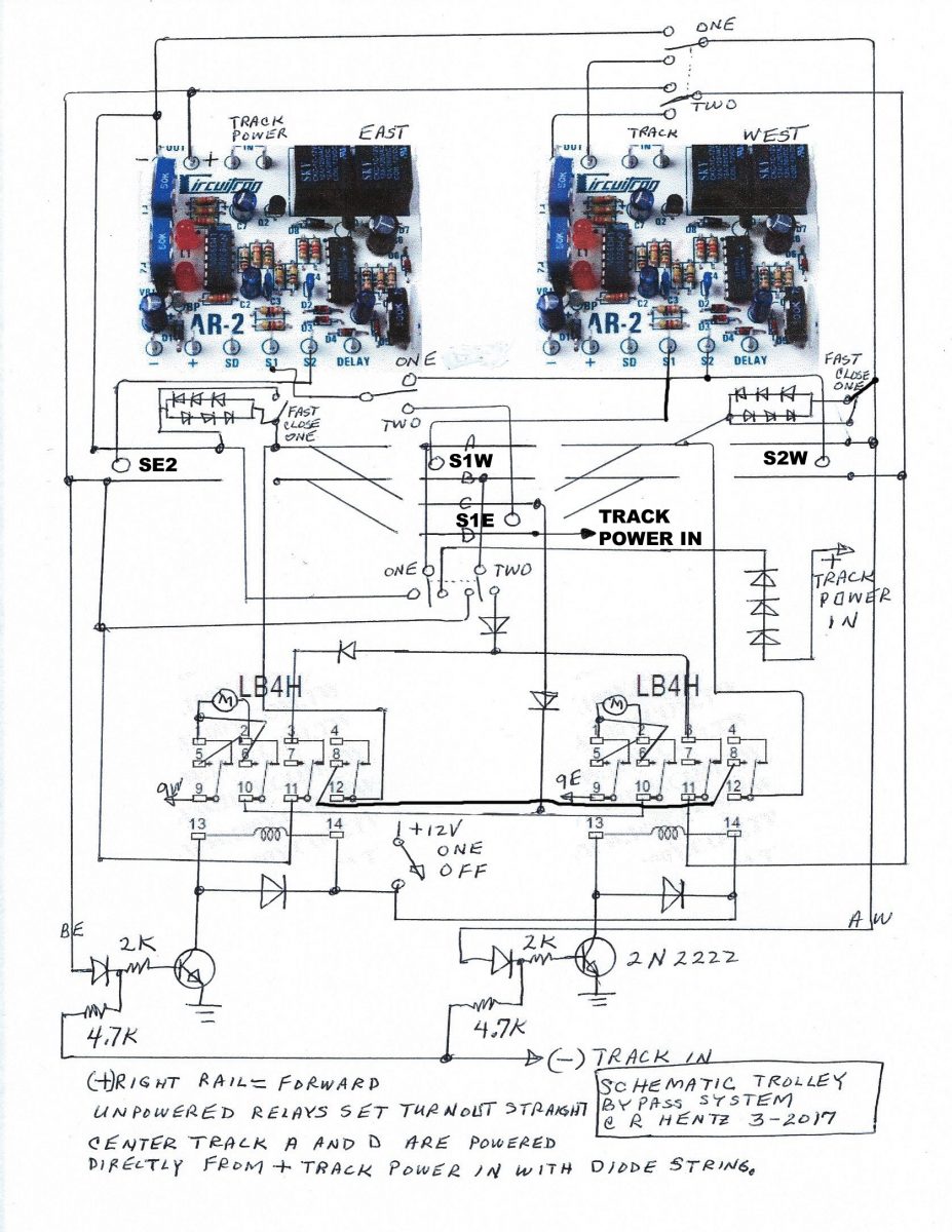
In the two trolley operation mode, since direction in the bypass is known, the A rail and the D rail will always be positive and slowed by a string of diodes. The relays then must direct only the negative power feed from the approaches to the section of the track that the turnouts are pointed to. The turnouts always follow the polarity of the tracked decided by the AR-2 reversers.
The relays are 12 volt 4 pole double throw type enclosed with a socket type base for easy removal and replacement. When the B rail goes positive, power will go through a blocking diode to the base of the transistor. This causes the transistor to start conducting allowing the relay coil to connect to the negative terminal of the 12 volt supply. This will close the contacts of the relay. Two poles are used to reverse the polarity on the turnout motors. The other two poles are used to direct track negative feed from the B rail to the B or C rail in the bypass. Only when the turnout position points to that section will that section get power from the B track approaching that section.
In the one trolley operation mode, only A and B rails are used and are supplied from the East AR-2 reverser. All power to the relays is off so they will direct the turnouts to go straight. The sensors are switched so that the far end sensor is now connected to the East AR-2 reverser. Also the slow approach sections have their diode strings shorted so that the speed is normal (fast).
The above circuit was designed and built by Charles R. Hentz. This system was successfully operated on April 4, 2017 for the first time.
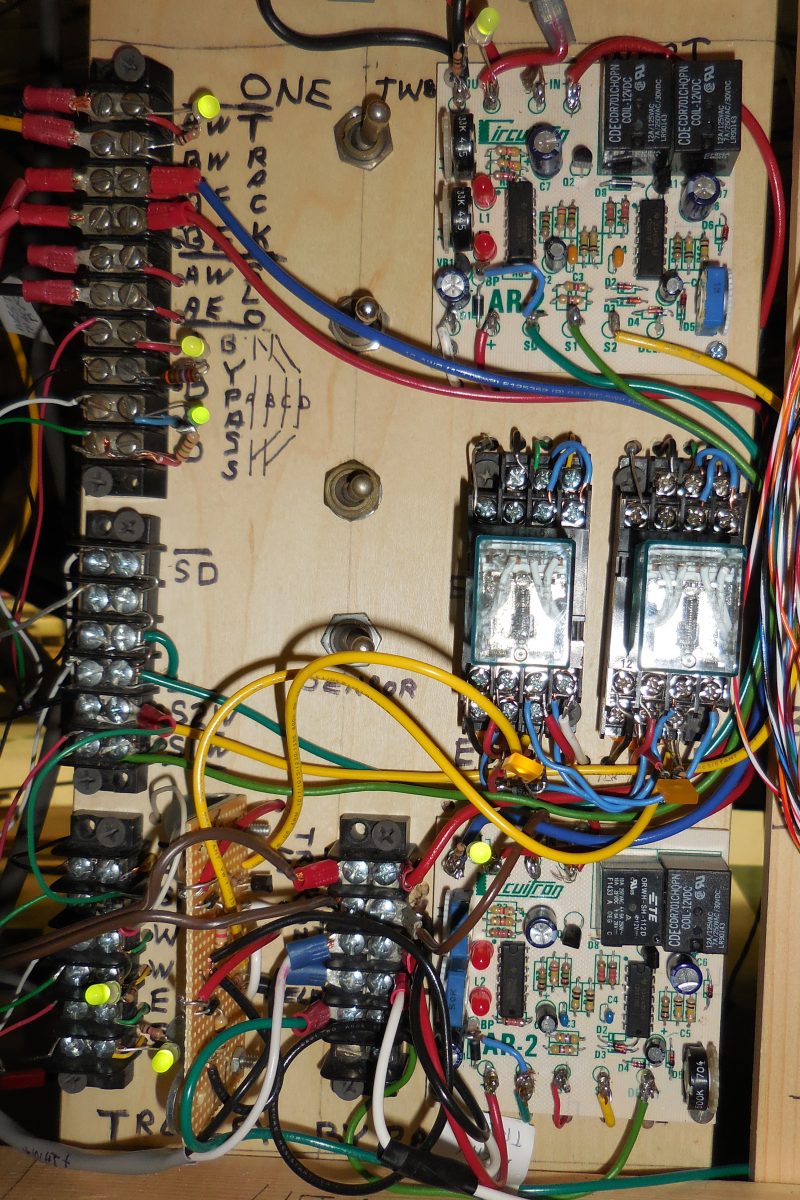
Circuit Board