Background and Theory for Dwarf Signals in Yard
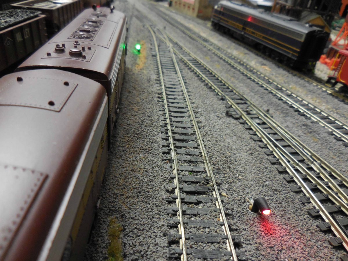
Tom Hawk asked for dwarf signals for the yard so that anyone could set the turnouts correctly and be sure that a derailment would not occur as a train left the yard onto Main Line. The dwarf signal if green, will act as permission to leave the stub track as all necessary turnouts are set for a clear path to main line.
Dwarf signals were made using black shrink wrap (3/32 inch and 1/8 inch). These were bent after 30 gauge wire wrap wire was attached to each lead of a bicolor 3 mm led and the 3/32 inch sleeve covered the leads. On the east panel under the yard, a terminal board with room for two screws for each of the eight motors of turnouts 5, 30,31,32,33,34,35 and 36. Under this was a row for two screws for each of the seven stub LEDs labeled one to seven. From this panel there is a cable of 50 conductors that goes to the logic circuit located under the large TV screen facing the aisle.
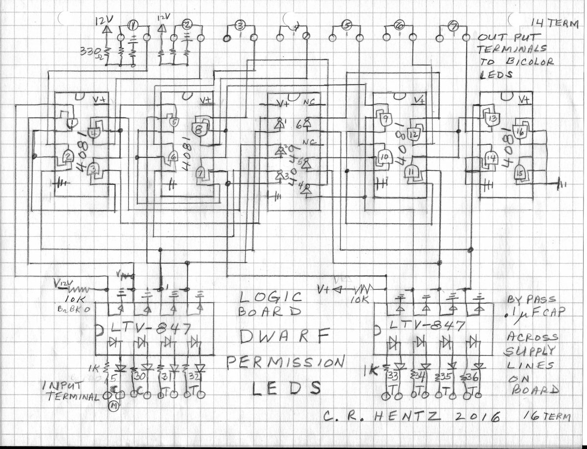
The circuit has the eight input lines from the turnout motors connected on the left terminal strip. These are inputs to LTV-847 which is an optical coupler to isolate Digitrax system from any electrical contact to the logic system. When the red LED is on, then the LED inside the integrated chip is conducting and causing the matching phototransistor to conduct like a switch being closed. This provides a low (ground) to any line on the output of this chip. When the red LED is not on, then the phototransistor does not conduct and there will be a high (3.3 volts) on the output line.
The truth table shows how the inverters (4049 ic) provide the necessary negative logic conditions so that an and gate (4081) gets a high if the a certain turnout is closed. The outputs on the and gates go to the middle of a voltage divider causing either a high or a low to make the current flow through the LED in either direction causing the color to change. All the dwarf LEDs have additional resistors (2K ohms) on the east panel board besides the resistors (330 ohms) which are on the circuit board.
The .1 microfarad capacitor across the supply voltage of 12 volts DC is necessary to eliminate transient spikes as the gates change their states. All unused outputs have been connected to ground.
Charles R. Hentz December 2, 2016 This is an original circuit.
Smart Dwarf Signals
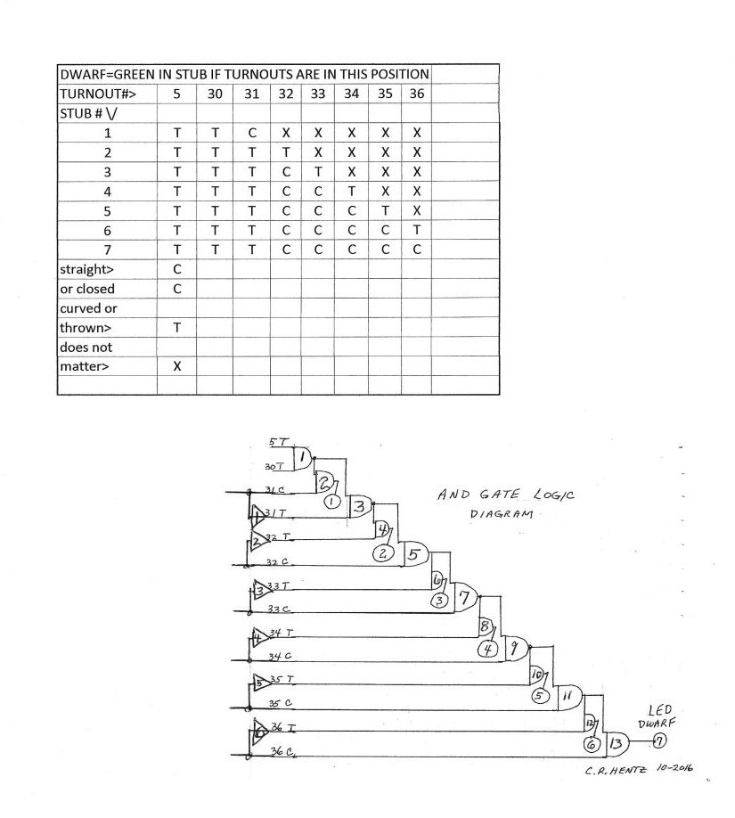
Truth Table and Logic Diagram
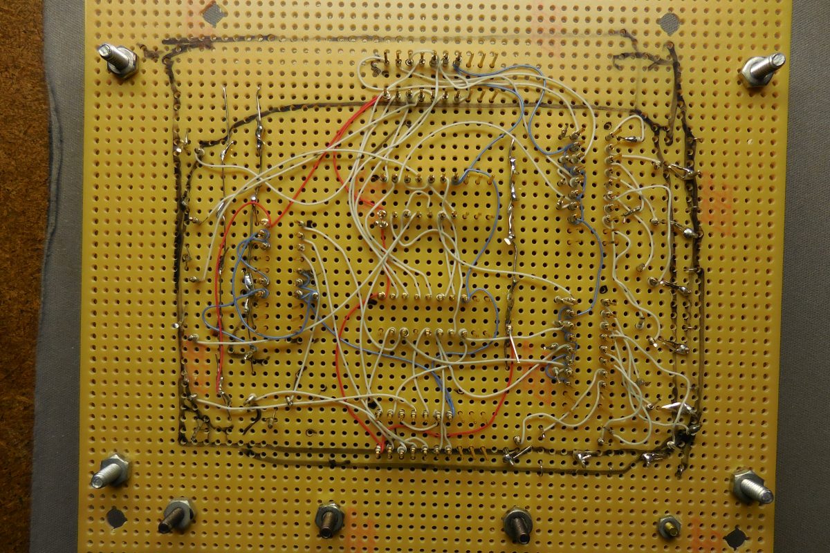
Schematic Layout
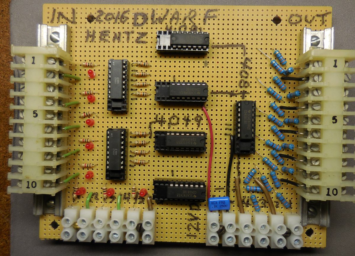
Layout Using Wire Wrap