Smart Turnout
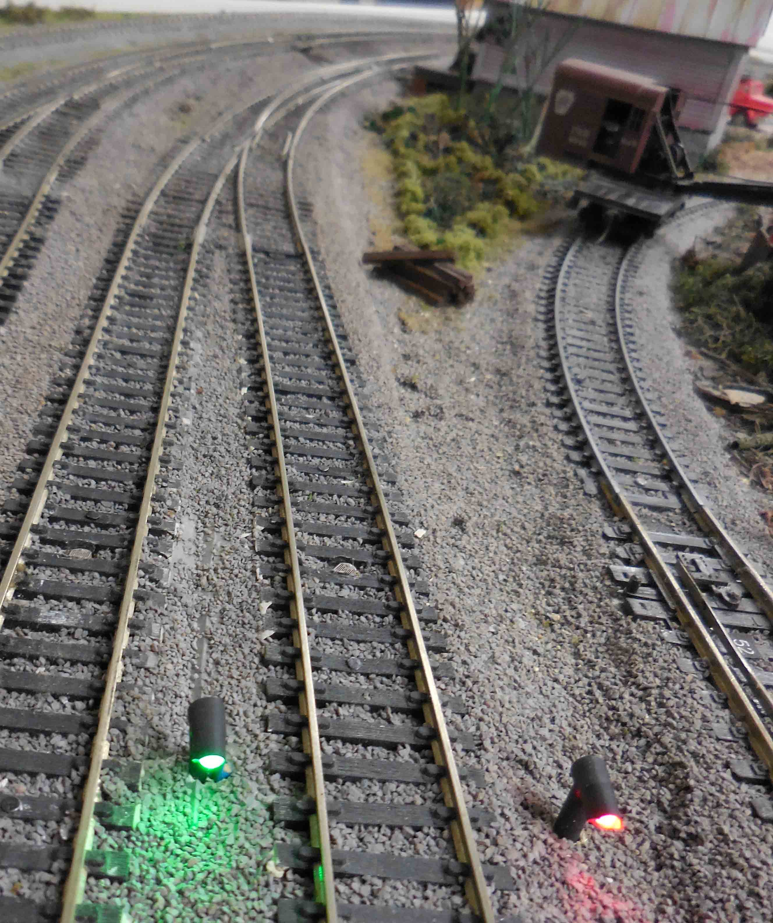
Problem: Two parallel tracks are converging to a single track and someone has not set the turnout to the correct position. When a train approaches this turnout that is set against its path, it will cause a derailment or a short circuit which sometimes scramble the decoders.
Solution: To prevent this, each approaching track will have a photo resistance sensor installed six inches before the turnout to sense an approaching train. If the sensor is dark AND the turnout is in the wrong position, then this circuit will activate the turnout motor to its opposite position.
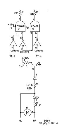
Circuit Theory: Connect the wires to the turnout motor at the DS64 so that if the train on the right is approaching a turnout that is in the correct position, the LED color is RED AND CONDUCTING. This will also cause the diode above to conduct giving the base of the NPN transistor a positive current. The transistor now conducts to the ground giving a low to pin 5 of the AND gate on the right. This low is also on pin 9 of the inverter which produces a high to pin 2 of the AND gate on the left. Since there is no real high when the transistor is not conducting, this circuit needs a pull up resistor to provide a high to the input of the inverter as well as to the AND gate to show the turnout is now in the wrong position. If the right sensor is dark, the Circuitron DT-4 rolling stock detectors will produce a low. This is sent to pin 5 of the inverter causing a high output to pin 6 of the AND gate. With both inputs high on the AND gate, the output will be high which activates the “S” input on the DS64 Stationary Decoder by Digitrax to throw this turnout. Since the “AND” gate will no longer have two positive inputs, the output returns to low very quickly. The AND gate on the left works in a similar fashion using the sensor on the left track to provide a low to pin 7 of the inverter and a high on pin 6 and pin 1 of the AND gate on the left.
C. R. Hentz Jan. 25, 2019
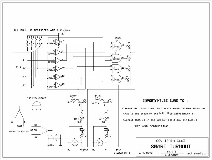
Smart Turnout Schematic
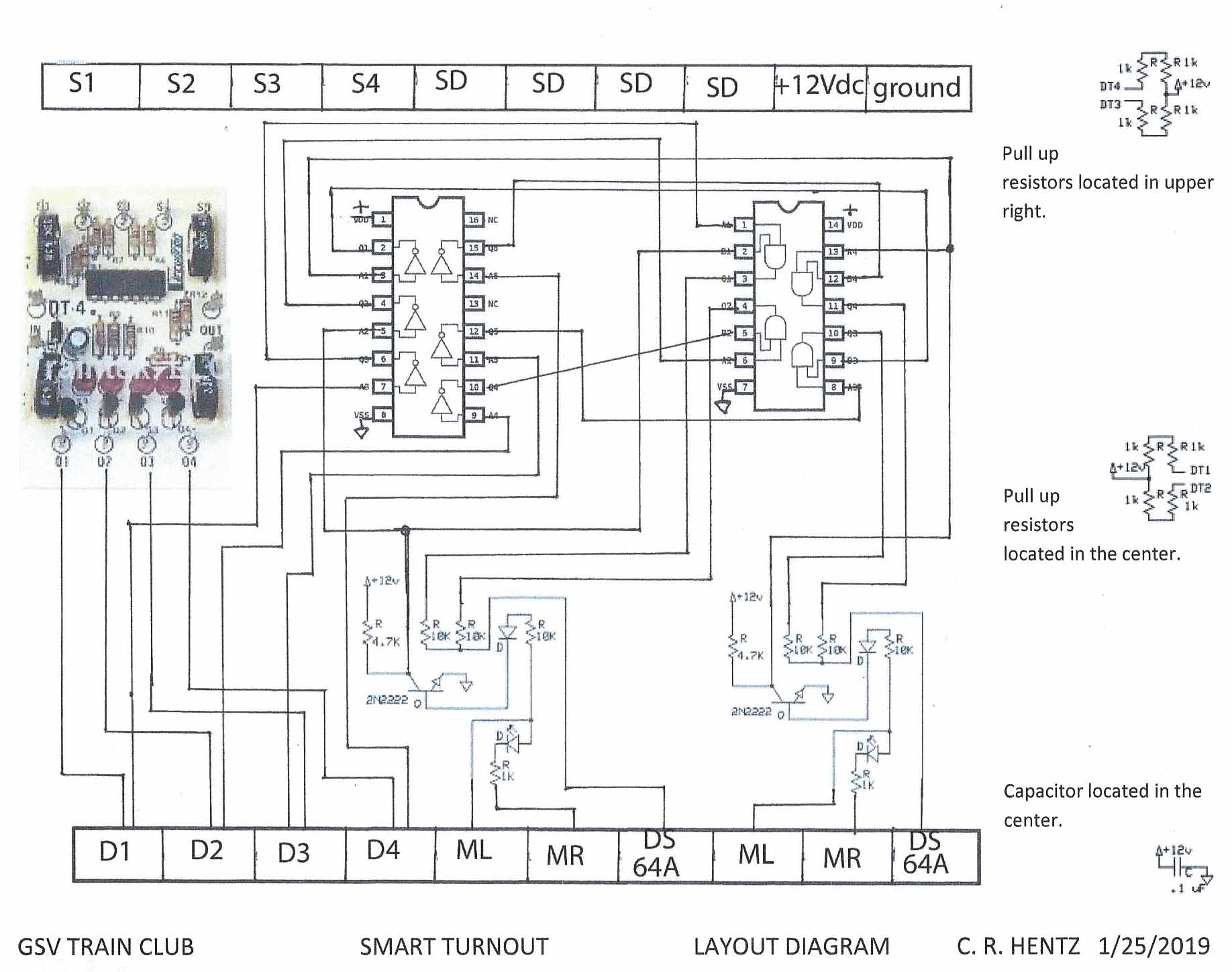
layout with resistors
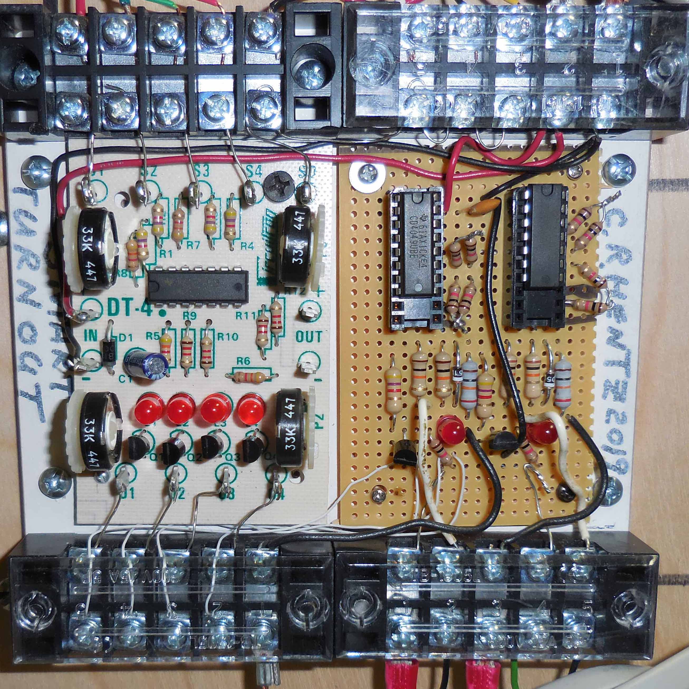
SmartTurnout Board