
Thomasville Double Train Control (aka Two Two Train)
by Charles R. Hentz
In order to control two trains on the same track with only one DC speed controller, a system was devised that can sense the movement of the trains and keep them separated as they circle the loop. The loop was divided into eight sections of track with gaps on the left side going forward so only the negative rail will be controlled. Infrared sensors (LM393 Module) were placed in each section to give the location of each train. The sections were labeled A through H on all panels and software programs. The system will cause the section immediately behind each train to go dead and the following section to have it’s speed reduced. Speed reduction is variable to ensure an even speed and allow for different motor characteristics of the two locomotives.
This hardware is near the Thomasville area mounted on a board accessible from the aisle. Since the original design used relays which had the contacts worn out in two years, this system uses TIP120 transistors which can handle five amperes of current. Also in 2022, the optical sensors were replaced due to shadows produced by visitors pointing to various scenery features. The infrared sensors are only effective for four inches above the track. Aluminum foil tape was applied to the under side of cars to better reflect the beam back to the sensor.
In case of failure of the entire system or individual sections, a row of bypass switches allows direct contact to negative rail. The Arduino Mega 2560 rev.3 microprocessor board provides ample memory and in/out line pins. These included the available 14 PWM (pulse width modulation) pins which are used to vary the slow speed when needed. In order to protect this microprocessor from the track power supply, an optical coupler isolation module TLP281 is used between the microprocessor board and the train power supply.
The Adafruit LEDBackpack was added to show the status of each of the eight sections of track using its 24 separate LEDs divided into sets of three which can be red, yellow, green or off. All of this bar can be controlled with only four connecting wires to the Arduino microprocessor.
Successful test operation of the above was completed on July 18, 2019 by Charley Hentz for a cost of about $90. New code was uploaded and wiring completed on Sept. 9, 2019. This an original circuit and code except for the required included code from Adafruit for the LEDBAR.
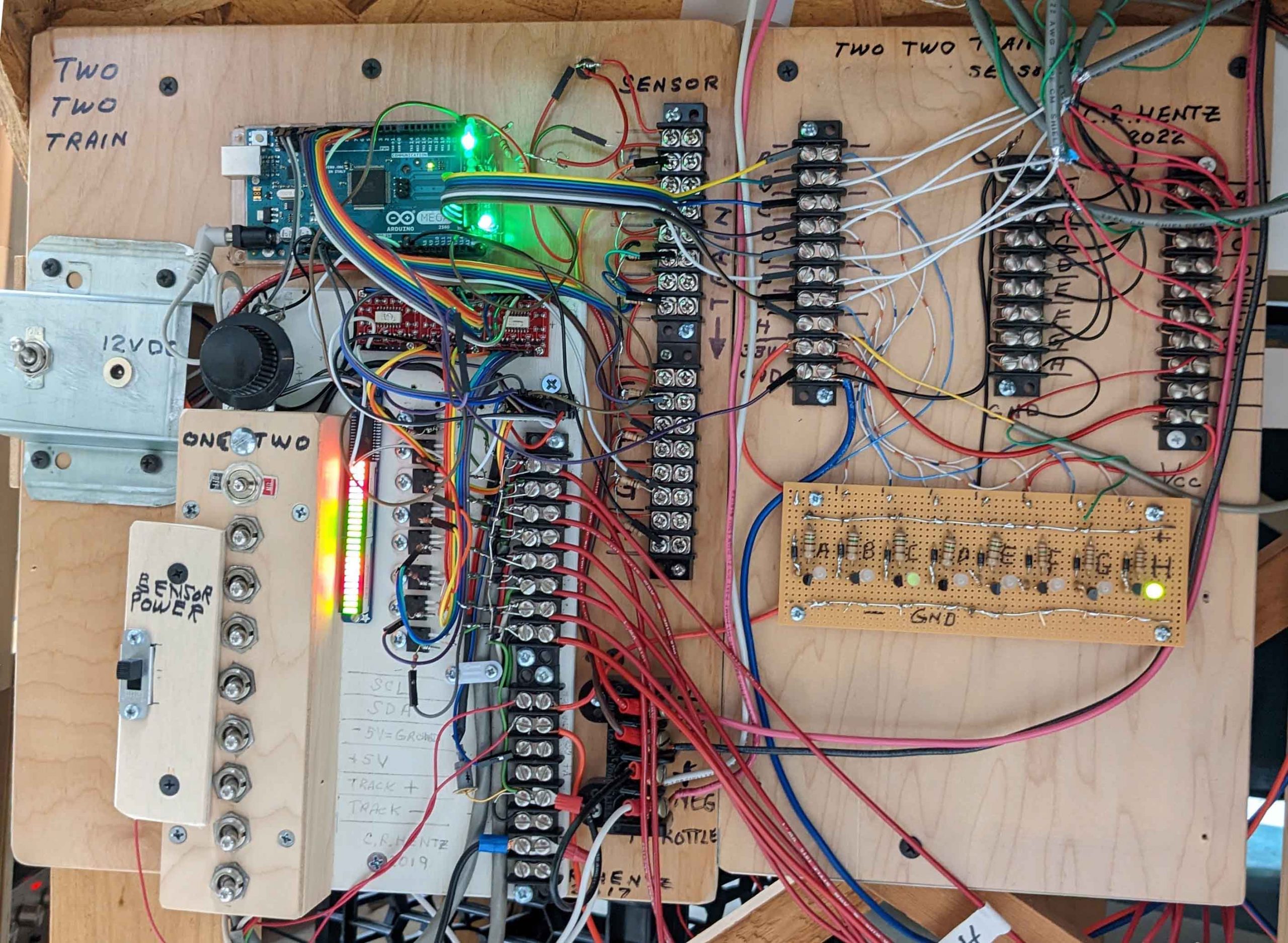
22 circuit panel
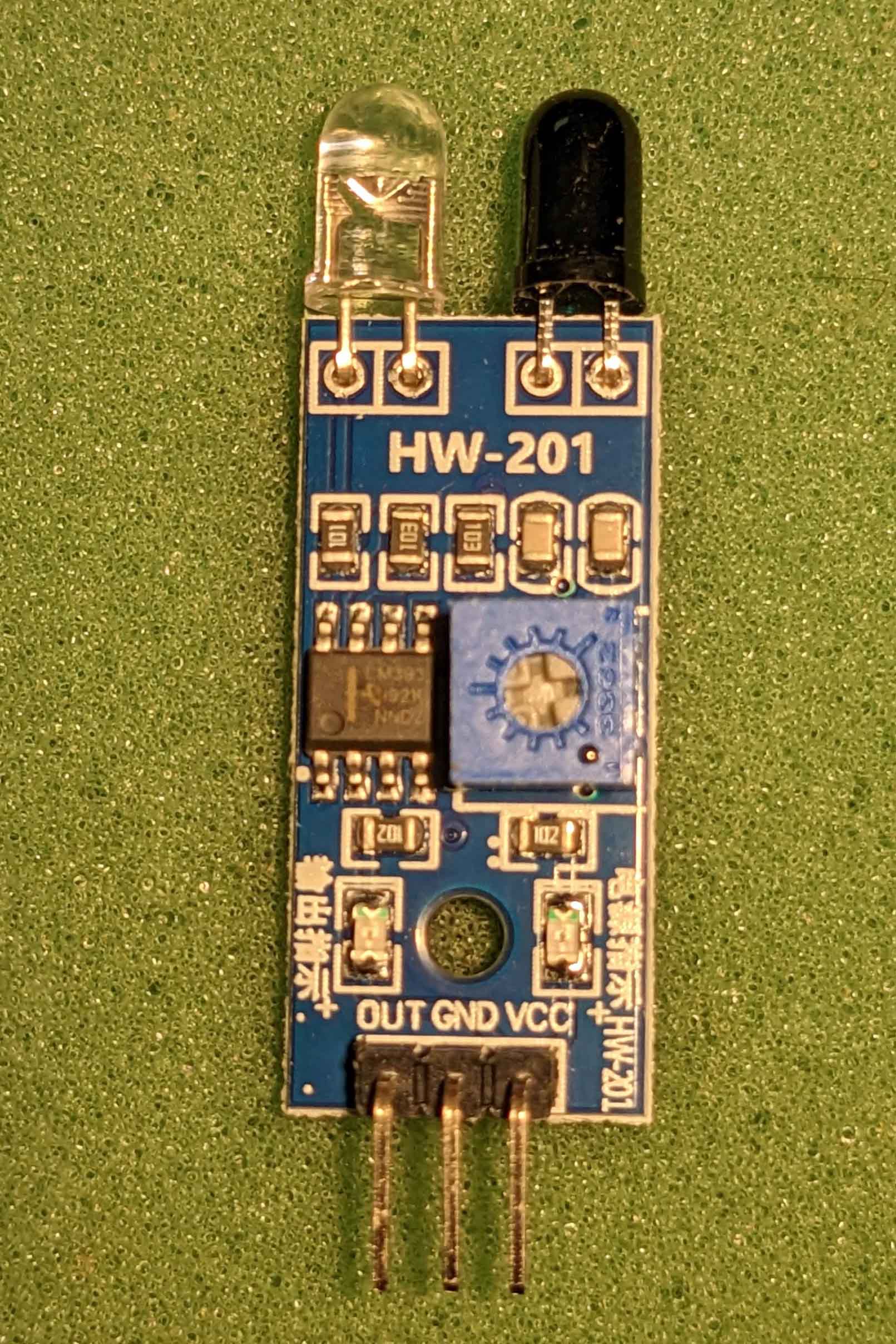
LM393 Sensor Module
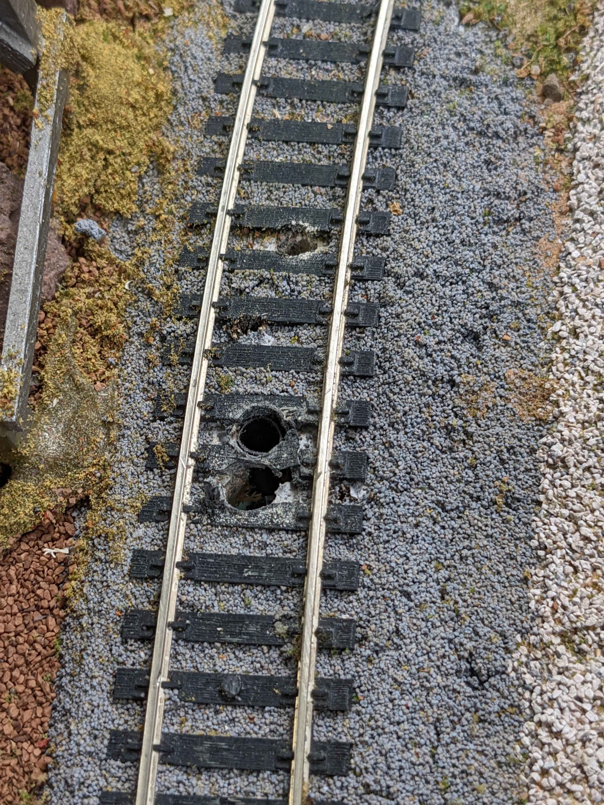
HO Track holes
1/4 inch holes for sensor
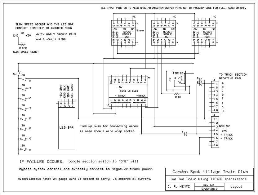
layoutTIP120
